
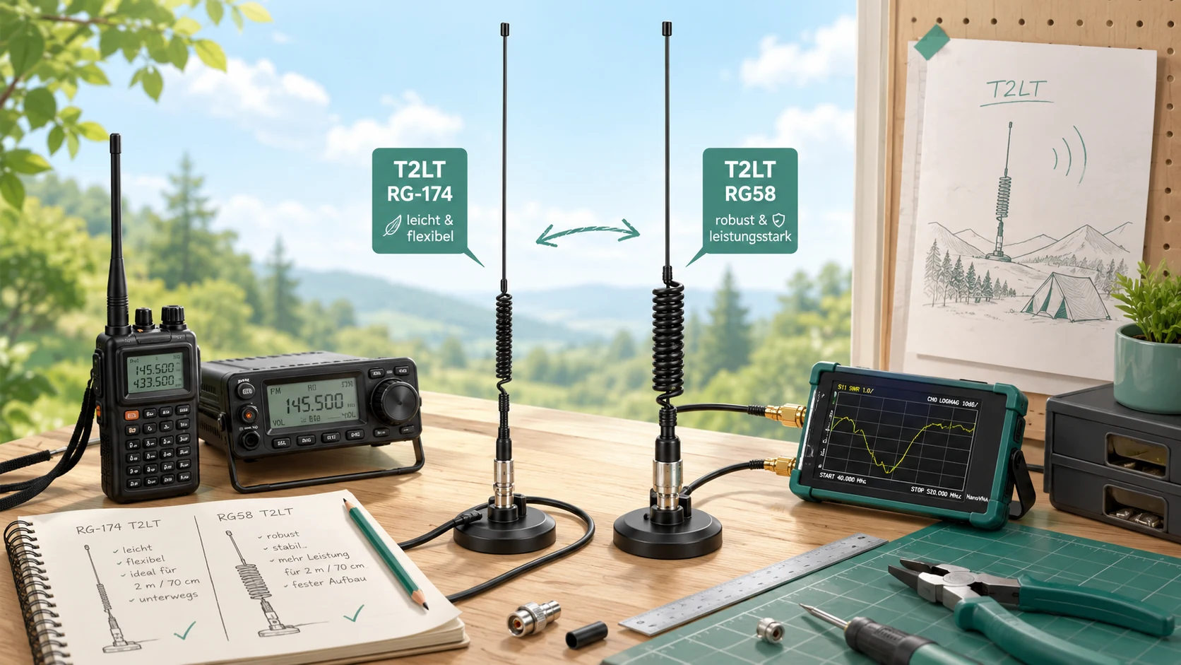
A useful antenna for 2 metres and 70 centimetres does not have to be expensive or complicated. That is exactly why I find the coax-based T2LT so interesting: with a few metres of coax, a short plastic former, some heat-shrink tubing and a suitable connector, I can build a vertically suspended antenna that works well as a lightweight portable option or as a simple extra antenna at home.
In this build guide I look at two versions. The first uses very thin RG-174 and is especially light and compact. The second uses RG58, making the antenna mechanically stronger and more suitable when robustness matters more than minimum weight. Both follow the same basic idea, but the choke dimensions and practical use differ.
What is a T2LT antenna?
T2LT stands for Tuned Transmission Line Trap. In simple terms, part of the coax cable becomes the antenna itself. At the top, the exposed insulated inner conductor forms one section of the radiator. A defined length of complete coax remains below it, followed by a coil made from the same cable. This coil acts as a common-mode choke and helps separate the active antenna section from the feed line.
When mounted vertically, the antenna provides the horizontal omnidirectional pattern that is useful for FM, repeaters and many other VHF/UHF applications. I like the concept because the mechanical construction stays extremely simple.
Version 1: lightweight RG-174 T2LT
For a backpack, fibreglass mast or spontaneous portable operation, RG-174 is particularly attractive. It is thin, flexible and packs down very small. A proven starting point used by radio amateurs is 43.5 cm of insulated inner conductor, 45 cm of complete coax and 9 turns on a former of about 25 mm diameter.
Materials for the RG-174 version
- RG-174 coax cable
- about 5 cm of plastic tube, roughly 25 mm outside diameter
- heat-shrink tubing
- thin cord for suspension and strain relief
- BNC or another suitable connector
- cutters, stripping tools, tape measure and drill
- soldering iron or crimp tool depending on the connector
- ideally a NanoVNA or another antenna analyser
Step 1: make the 43.5 cm upper radiator
I measure 43.5 cm from the future top end of the antenna. Over this section I carefully remove the outer jacket and braid while keeping the insulation around the centre conductor intact. The result is a 43.5 cm insulated centre conductor forming the upper section.
Step 2: measure another 45 cm of complete coax
From the point where the braid ends, I measure another 45 cm. This remains complete RG-174. The total length from the antenna tip to the start of the choke is therefore 88.5 cm.
Suspension
    │
43.5 cm
inner conductor
    │
45 cm RG-174
    │
9 turns
about 25 mm diameter
    │
Feed line
Step 3: nine turns on a 25 mm former
The common-mode choke starts immediately after the 88.5 cm antenna section. I use a short piece of plastic tube around 25 mm in diameter and wind the RG-174 around it nine times. The turns should sit neatly next to each other without crossing.
Step 4: suspension and strain relief
I do not want the thin centre conductor taking the mechanical load, so I attach a light cord to the choke former and run it towards the top. Heat-shrink tubing can secure both the coil and the upper antenna section. This makes the very lightweight construction much more practical in real portable use.
Version 2: the more robust RG58 T2LT
If size and weight matter less, I find the RG58 version equally interesting. It is mechanically stronger and the feed line has lower loss than RG-174. Experiences shared by radio amateurs suggest starting with roughly two 50 cm antenna sections before the choke and nine turns of RG58 on a former of about 20 mm diameter.
I would treat these RG58 dimensions as a starting point rather than universal millimetre-perfect numbers. Building, measuring and adjusting is more important here than copying a value without checking the finished antenna.
Materials for the RG58 version
- RG58 or RG58 C/U coax
- plastic tube around 20 mm diameter
- heat-shrink tubing or other securing material
- suitable coax connector
- optional larger plastic tube for weather protection
- basic cutting and stripping tools
- NanoVNA or another antenna analyser
Step 1: start with roughly 2 × 50 cm
I would begin with approximately 50 cm for the upper section and another 50 cm for the lower section. I prefer leaving a little extra material at first. I can shorten it later after measuring.
Step 2: nine turns on 20 mm
The choke again uses nine turns, but this time on a former of about 20 mm diameter. With the thicker RG58 this produces a noticeably more substantial coil.
Step 3: optional protective tube
For a more permanent installation, I like the idea of putting the complete RG58 antenna inside a plastic protective tube. Experiences from other amateur radio operators suggest this can make the construction much less sensitive to rain and mechanical damage. Any permanent outdoor installation still needs proper sealing around openings and cable entries.
Can one antenna really cover 2m and 70cm?
This is where I would avoid making absolute promises. The physical dimensions are clearly related to the 2-metre band, while usable results on 70 centimetres are often attributed to a higher-order resonance. Radio amateurs have reported useful dual-band behaviour, but I would never assume that every build will automatically be perfect on both bands.
That is why I would always measure at least 144–146 MHz and 430–440 MHz after construction. A NanoVNA makes it easy to see not only SWR but also where the actual resonances sit.
RG-174 versus RG58
| Property | RG-174 | RG58 |
|---|---|---|
| Weight | very low | higher |
| Pack size | very small | larger |
| Flexibility | very high | lower |
| Mechanical strength | ideal portable | more robust |
| Feed-line loss | higher | lower |
| Choke | 9 turns / ~25 mm | 9 turns / ~20 mm |
| Starting dimensions | 43.5 + 45 cm | about 50 + 50 cm |
| Typical use | backpack / portable | portable / stronger installation |
For a backpack I would choose RG-174. For a more robust mast installation or an antenna that spends more time outdoors, RG58 is attractive. The final decision depends much more on the intended use than on the idea that one cable is universally better.
Mounting height matters
On VHF and UHF, mounting height and a clear location can matter at least as much as the last few percent of antenna efficiency. I would rather use a simple T2LT mounted high and clear than a theoretically perfect antenna close to the ground or surrounded by metal.
How I would tune it with a NanoVNA
- Hang the antenna vertically in a clear position.
- Measure a wider range around the 2-metre band.
- Check resonance and SWR between 144 and 146 MHz.
- Then inspect 430 to 440 MHz.
- Only adjust the dimensions when resonance is clearly misplaced.
- Make small changes and measure again after every adjustment.
My conclusion
I like this kind of antenna project because it demonstrates how little material is needed for a genuinely useful amateur radio antenna. The RG-174 version is extremely light and portable, while the RG58 version is stronger and better suited to a more permanent construction.
The important numbers are easy to remember: RG-174: 43.5 cm + 45 cm + 9 turns on about 25 mm. For RG58 I would start with roughly 2 × 50 cm and 9 turns on about 20 mm, then measure and tune the finished antenna.
The most interesting next step would be a real A/B test: same location, same height, same radio and both antennas one after the other. That is where a build guide becomes a meaningful practical comparison.